Anclajes Autoperforantes de Inyección TITAN
Los micropilotes autoperforantes TITAN, pueden utilizarse en gran medida para mejorar los terrenos. La mejora del terreno por medio del cuerpo interconectado de la lechada y las barras autoperforante permite que la tensión, la compresión y las cargas cíclicas se transfieran al suelo in situ.
La calidad de los micropilotes TITAN están sustentados ó cubiertos por la Aprobación Técnica Nacional Z-34.14-209 emitida por el DIBt. Este es el único sistema de pila agrupada tubular que también se puede utilizar para aplicaciones permanentes de más de 100 años.
Aplicaciones de Barras TITAN
CIMENTACIONES Y APUNTALAMIENTO
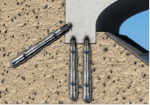
ANCLAJES
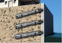
SOIL NAILING
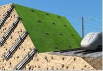
TUNELIZACIÓN Y MINERÍA
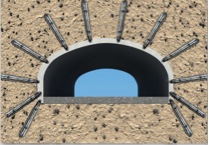
PANTALLAS DE TABLAESTACAS
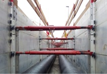
ENCONFRADA
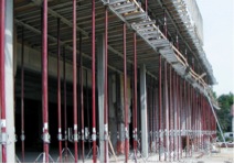
Datos Técnicos: TITAN Hollow Bar

Designation |
Unit |
TITAN 30/16 |
TITAN 30/11 |
TITAN 40/20 |
TITAN 40/16 |
TITAN 52/26 |
TITAN 73/56 |
TITAN 73/53 |
TITAN 73/45 |
TITAN 73/35 |
TITAN 103/78 |
TITAN 103/51 |
TITAN 103/43 |
TITAN 127/103 |
Nominal outside diameter Dsteel |
mm |
30 |
30 |
40 |
40 |
52 |
73 |
73 |
73 |
73 |
103 |
103 |
103 |
127 |
Nominal inside diameter Dsteel |
mm |
16 |
11 |
20 |
16 |
26 |
56 |
53 |
45 |
35 |
78 |
51 |
43 |
103 |
Effective crosssection Aff |
mm2 |
340 |
415 |
730 |
900 |
1250 |
1360 |
1615 |
2239 |
2714 |
3140 |
5680 |
6024 |
3475 |
Ultimate load Fu |
kN |
245 |
320 |
540 |
660 |
925 |
1035 |
1160 |
1575 |
1865 |
2270 |
3660 |
4155 |
23204) |
Characteristic loadcarrying capacity Rk according to German approval document1) |
kN |
1552) |
225 (250)3) |
372 |
465 |
620 |
6952) |
860 |
1218 |
1386 |
1550 |
2325 |
30152) |
18002) |
F0,2.k force at 0.2 % proportionality limit (mean value) |
kN |
190 |
260 |
425 |
525 |
730 |
830 |
970 |
1270 |
1430 |
1800 |
2670 |
3398 |
2030 |
Strain stiffness E·A5) |
103 kN |
63 |
83 |
135 |
167 |
231 |
251 |
299 |
414 |
502 |
580 |
1022 |
1202 |
640 |
Bending stiffness E·I5) |
106 kNmm2 |
3,7 |
4,6 |
15 |
17 |
42 |
125 |
143 |
178 |
195 |
564 |
794 |
838 |
1163 |
Weight |
kg/m |
2,7 |
3,29 |
5,8 |
7,17 |
9,87 |
10,75 |
13,75 |
17,8 |
21,0 |
25,3 |
44,6 |
47,3 |
28,9 |
Length |
m |
3 |
2/3/4 |
3/4 |
2/3/4 |
3 |
6.25 |
3 |
3 |
3 |
3 |
3 |
3 |
3 |
Left- / right-hand thread |
– |
left |
left |
left |
left |
left right |
right |
right |
right |
right |
right |
right |
right |
right |
1) The load-carrying capacities must be reduced according to National Technical Approval Z-34.14-209 in the case of permanent tension loads and cement grout cover c < 45 mm.
2) An approval for these sizes is not yet available. The values were interpolated in a similar way to the approval for TITAN 30/16, 73/56 and 127/103 micropiles.
3) A characteristic load carrying capacity Rk = 250 kN may be used for TITAN 30/11 in temporary installations.
4) Only applies to hollow steel tendon without coupling nut. The ultimate load is 2048 kN for coupled hollow steel tendons.
5) The values are to be used in the case of deformation calculations. These values were determined in tests. It is not possible to calculate the modulus of elasticity, cross-sectional area or moment of inertia from these figures.
| Note: | Shear Force | Certified to | ||||||
| Subject to change without notice. | Allowable shear force is determined by the formula: | ISO 9001 | ||||||
| Qallow= | Yield T₀₂ * A A=Area | |||||||
| 1.75 * √3 | ||||||||

